The GM11 Table
History
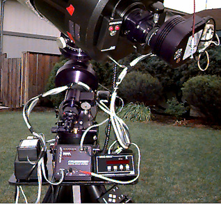
The idea for this table arose while trying to solve the problem of what
to with the ST-7 power supply. I used to the keep the supply and the relay
interface strapped onto one the the GM11 legs. While this did work, it
was messy and difficult to install and remove. Looking at the mount, I
decided a table could be constructed that would not only hold the power
supply, but also other peripheral gear such as the DSC computer, eyepieces
and what not.
Requirements
My requirements for the table were:
It is must be easy to install and remove.
It should be sturdy.
It should be big enough to hold the power supply, the DSC computer, eyepieces
and other small things.
No permanent modifications (holes, etc.) could be made in the mount
It needed to avoid getting in the way of the OTA and counter weights in
all possible positions.
It should be compact so as not take up a lot of room if I ever take the
mount off to dark site.
This table meets all of these requirements.
Construction
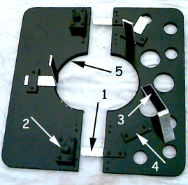 This picture shows the bottom of the table.
The table size was determine by making cardboard mockups and testing
them on the mount to insure that the table did not get in the way of the
OTA and counter weights. I found that 17" x 14.5" would work very well.
The table is held together by sliding the metal bar (1) into the bracket
(2) and an then tightening the screw on (2) down onto the bar. The bracket
is made of wood. Height spacers made from the same stock as the metal bar.
The screw is 1/4 x 20 cap screw with push-on plastic knob. Brass 1/4 x
20 thread insert were placed in to wooden bracket to hold the screw.
The three table supports (3) are designed to slide into and back and
forth under the brackets (4). The supports, brackets and bracket spacers
are all made from same metal bar material as (1). One support is shown
removed from under its bracket. The mount side of the supports have stick
on Velcro attached. The mount has matching Velcro strips to mate with the
support Velcro. The supports are bent a angle slightly greater than
90 degrees.
The hole (5) is cut slightly larger than the diameter of the mount and
lined with a soft material.
Installation
To install the table on the mount
Slide the supports back away from the center hole.
Push the two table sides together around the mount slipping (1) under (2)
and tightening the screws on (2) to hold the two halves together.
Align and level the table as needed.
Push each of the three supports towards the mount to meet the matching
Velcro strips on the mount. Push firmly to join.
Removal
To remove that table
Loosen the screws at (2)
Pull the single support on the front half of the table back from the mount.
Pull the front half of the table off.
Pull the two supports on the back half of the table back from the mount.
Remove the supports and pack up.
Back to the CG11 Page